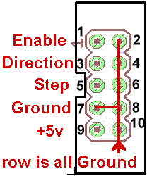
Almost all motion control uses just 2 signals: Step and Direction although a 3rd Enable line is often used as well.
Each pulse on the Step line tells the motor to move one increment in the direction specified by the Direction line.The Enable line can be used (or ignored) to power or release the motor at the driver.
These pins are sometimes referred to by other names:
Step: Pul+, Pulse, Clock, CLK, etc..
Direction: CCW+, Dir, etc...
PMinMO is a standard pinout defined by Phil Moore from .mo for Step and Direction signals, as well as logic power and Enable. It uses a standard 2x5 box header with pins on 0.1" or 2.54mm centers. When used with IDC connectors on ribbon cable, the back row of grounds on the even pins provides alternating shielding for the signal pins on the odd numbered connectors.
While not always named, this layout is often used in the connection between a motion controller and stepper or servo motor drivers.

See also:
| 2 GND | 4 GND | 6 GND | n/c | PMinMO | ||||
---- |
||||||||
|
|
|
|
ClearPath data cable Tab at top Colors may change |
||||
|
|
|
|
|||||
| 1 En | 3 DIR | 5 STEP | n/a | PMinMO | ||||
| file: /Techref/io/PMinMO.htm, 4KB, , updated: 2023/3/29 13:29, local time: 2025/11/1 03:04,
216.73.216.2,10-1-135-75:LOG IN
|
| ©2025 These pages are served without commercial sponsorship. (No popup ads, etc...).Bandwidth abuse increases hosting cost forcing sponsorship or shutdown. This server aggressively defends against automated copying for any reason including offline viewing, duplication, etc... Please respect this requirement and DO NOT RIP THIS SITE. Questions? <A HREF="http://ecomorder.com/techref/io/PMinMO.htm"> PMinMO Step / Direction Connector Standard</A> |
| Did you find what you needed? |
Welcome to ecomorder.com! |
|
Ashley Roll has put together a really nice little unit here. Leave off the MAX232 and keep these handy for the few times you need true RS232! |
.