Copyright ©, 2005 by
EDV-Beratung GmbH
Copyright ©, 2005 by
EDV-Beratung GmbH
Im Eulenflug 25
D-51399 Burscheid, Germany
Phone/FAX: +49 2174 - 785 931
eMail: g.daubach@mda-burscheid
Home: www.g-daubach.com
RS-232 I²C Adapter/Monitor
Revision 3.21
This adapter provides an easy-to-use interface between devices on an I²C bus and an RS-232 serial communications port of a PC, or any other device with a serial port.
The adapter's command set contains various options to interact with the I²C bus. The so-called "high-level" commands perform the necessary tasks for complete communications with I²C devices transparent to the application controlling the RS-232 side. This means setting the start condition, sending the address and the read/*write bit, sending or reading data bytes reading or setting the acknowledge bit, and finally generating the stop condition is completely handled by the adapter.
As the adapter returns results with a leading "O" in case of successful operations, or an "E" in case of errors, data read from an I²C device must be buffered in the adapter's memory before transmitting it via RS-232. This buffer has a size of 16 bytes, i.e. the maximum number of bytes that can be read from an I²C device with a high-level command is limited to 16.
The adapter command set also contains so-called "low-level" commands to interact with the I²C bus "more directly". Such commands require a bit more activities on the RS-232 side. They allow for any number of data bytes transferred to or from an I²C device. They are also useful to communicate with I²C devices that expect sequences other than the ones handled by the "high-level" commands.
Besides its major task to translate between RS-232 and I²C, the adapter also accepts commands via RS-232 to set five parallel output lines, and to read eight parallel input lines. The input lines also clock eight internal 16-bit counters which can be read, or reset by designated commands.
For debugging, or test purposes, a "Monitor Mode" can be activated which turns the adapter into an I²C "spy". In this mode, activities on the monitored I²C bus are transmitted via the RS-232 interface.
As an option, a serial EEPROM, pin-compatible to 24LC01, 24LC02, etc. devices can be installed on- board.
The adapter makes use of an SX28 micro controller. Therefore, by modifying the controller software, the adapter can easily be adapted to special customer requirements.
Since version 3.2, the adapter is built on a 4-layer PCB with one inner layer connected to Vdd (positive supply), and the other layer connected to Vss (ground). This technology makes sure that international EMC regulations are met and it also increases the noise immunity of the adapter.
Important Notice: When possible, do not drill additional holes into the PCB in order to avoid possible shortages between the two inner layers. If this can't be avoided, please double-check that there is no short between the positive and negative supply signals. Should this be the case, carefully widen the drilled hole until the short is gone.
Electrical Specifications
Supply voltage:
3.3 to 5 V DC stabilized, or 8...12 V DC, non-
stabilized, approx. 100 mA (with an additional
voltage regulator installed), or 8...36 V DC
(with an additional DC/DC converter installed).
Maximum voltage on all pins:
7 V
Parallel
inputs:
TTL
level
with
Schmitt-Trigger
characteristics,
controller-internal pull-up resistors (approx. 10
kOhm) against the positive supply voltage.
Parallel outputs:
TTL-level, maximum current, outputs can
sink or source: 30 mA.
Note: When switching inductive loads like relays, suppressor diodes are
required .
Serial interface:
+/- 12 V, according to the RS-232 specifications.
115.2 kBaud (optional 38400 Baud), 8N1, no handshake
Interface to the PC
Communication with the PC is performed via the TxD and RxD signals of an RX-232 serial port at 112.5 kBaud (or 38400 Baud), 8 bits, no parity, one stop bit. There are no handshake lines required.
The adapter's 9-pin SUB-D jack must be connected to a COM port of the PC, using a "straight through" serial cable. A "Null Modem" cable will not work.
I²C Interface
For communication via the I²C bus according to the specifications of Philips, the signals
Serial Data (SDA)
Serial Clock (SCL)
are available. Both signal lines are open collector. On the adapter, both lines are connected to the positive supply voltage via pull-up resistors. When pull-up resistors already exist elsewhere on the bus, the adapter's pull-up resistors can be de-activated by removing two on-board jumpers.
Parallel Inputs, Counter Inputs
One 8-bit input port of the controller is available to directly read parallel input data. These inputs are connected to the supply voltage via internal pull-up resistors (approx. ca. 10 k) and have Schmitt- Trigger characteristics.
Each of these eight inputs also control eight internal 16-bit counters. On each positive transition (low high) on an input line, the associated counter is incremented by one. Commands are available to read or clear one or all of these counters. The inputs are sampled at a rate of about 1 MHz, and don't have any de-bouncing provisions. If necessary, external components must be provided to avoid that "spikes" cause false counter results.
Parallel Outputs
Fife output port lines of the controller can be used to directly control external components, bypassing the I²C bus. These outputs can sink or source up to 30 mA each. When the adapter is powered up, or when in idle mode, the outputs are switched to high-impedance with no output voltage. After the first OUTPUT command has been received via the RS-232 port, the outputs switch to high, or low level, according to the parameters received with the OUTPUT command.
General Information About I²C Communications
Via the I²C bus one or more so-called "Masters" communicate with one or more so-called "Slaves". Here, the I²C adapter is supposed to be the only master in the system, and all I²C components con nected to the bus must act as slaves, i.e. they are supposed to react on commands that are sent from the PC via the adapter.
When a master wants to establish a communication, it first generates a start condition on the bus (SDA 10 while SCL = 1), and then sends an address/mode byte having the following format:
aaaaaaam
where "aaaaaaa" is the 7-bit address of the selected slave, and "m" indicates a read or write operation (m = 0: write, m = 1: read). After having received this byte, the selected slave pulls low the SDA line for acknowledge, and the master checks if the slave has acknowledged. If this is not the case, there is an error (slave not ready, not existing, having a different address, or some other fault).
When the master has initiated a write operation, it sends one or more data bytes following the address/mode byte, where each of these bytes must be acknowledged by the slave. At the end of a transmission, the master generates the stop condition on the bus (SDA 01 while SCL = 1).
When the master has initiated a read operation, it receives one or more bytes from the slave, and sends an acknowledge for each of these bytes except for the last one. By not sending an acknowledge for the last byte, the master indicates the slave not to send more bytes. Finally, the master generates the stop condition on the bus (SDA 01 while SCL = 1).
Further options of the I²C protocol, like clock-stretching, 10-bit addresses, multi-master mode, or handling of bus arbitrations are not required here, and are not supported.
IMPORTANT NOTE: The commands that communicate with I²C components expect a 7-bit address, i.e. the most significant bit must always be 0. This address value is automatically shifted one bit position to the left, and the lowest bit will be set on read, or cleared on write commands.
Purpose of the RS-232 I²C Adapter
Besides converting the electrical levels, i.e. from ±12 V to 0/+5 V for the TxD and RxD RS-232 signals, the major task of the adapter is to make the communication with components on the I²C bus as transparent as possible to the application running on the PC. This application can communicate with the adapter by using simple command sequences, that could be generated by a Visual BASIC application, for example.
The application sends a command character (plus some more characters, depending on the command) to the adapter. Commands that address the adapter itself are immediately acknowledged, where I²C commands issue the adapter to start a communication on the I²C bus. When this communication is completed, the adapter first returns a status character ("O", or "E") indicating if the operation was successful or not.
In case the operation was successful, the adapter returns one or more result bytes. In case of an error, the adapter returns just the error code "E".
Idle Mode
When the adapter is powered up, has received a BREAK command, after a time-out, or a reset, it enters the "Idle" mode, i.e. the I²C bus is held in idle condition (SDA and SCL both at high level), and no communication will be performed via the I²C bus. All commands received via RS-232 are answered with "S" (except the INIT command), and the status LED blinks.
To terminate the idle mode, an INIT command must be sent. This command sets some adapter parameters. After an INIT command has been received, the adapter accepts other commands via the RS-232 interface, and the status LED lights steadily.
It is also possible to turn the adapter from "Idle" directly into the "Monitor" mode (see the MONITOR command).
Time-Out
The INIT command allows the definition of a time-out value. When the specified time-out interval elapses before the adapter has received a new valid command via RS-232, it will enter the "Idle" mode, i.e. no more I²C communications are performed.
The PC application on the other hand, should also perform a time-out check. When it does not receive acknowledges from the adapter within a certain time interval, it should send a BREAK, followed by a new INIT command in order to reset the adapter.
Adapter Commands
This section describes the available adapter commands, where the following syntax is used:
<Character(s)> » = Character(s) that
are sent to the adapter
» <Character(s)> = Character(s) that
are returned from the adapter
When alternative values are possible, the "|" is used to separate them.
When a letter, a figure, or a special symbol is specified as <Character>, it will be transmitted or received as ASCII character (IMPORTANT: Upper and lower case is significant). When an expression like CHR(nnn) is specified instead, the binary, or ASCII code nnn will be sent or received instead. "CR" means that the Return character code (13) must be sent.
When two or more characters are sent or received, they are separated by plus signs "+" in the descriptions below, for better readability, but these plus signs must not be sent, and they are not received either.
Parameters enclosed in curly braces "{" and "}" are optional, they may occur zero, one or more times.
BREAK
Sequence:
This is a special function that allows to reset the adapter, independent from its current state. To perform a Break, the PC application must hold low the TxD line for more than 10 bit cycles after sending a start bit. This causes that the adapter does not receive a stop bit after the expected time which will result in a "framing error", thus causing the adapter to reset.
The PC application may send a null byte at a low baud rate (e.g. 300 Baud), or hold the TxD line low long enough. The MSComm object in Visual Basic has a Break method for this purpose.
After the adapter has detected a BREAK, it acknowledges this by returning an "O", and then enters into idle mode until it receives a new INIT command.
Other commands sent from the PC while the adapter is in idle mode are acknowledged by an "S" ("S"leep) returned from the adapter, except for the MONITOR command, which activates the Monitor mode.
CLEAR ALL COUNTERS
Sequence:
Function: Clears all counters.
Returns: O = Success
This command clears all eight internal 16-bit counters that are associated to the inputs.
CLEAR COUNTER
Sequence:
Allowed values for <n>: 0...7
Function: Clears the counter that is assigned to the input specified with <n>
Returns:
This command clears the 16-bit counter that is associated to the input specified with <n>.
COUNTER READ
Sequence:
Allowed values for <n>: 0...7
Function: Reads the contents of the counter that is assigned to the input specified by <n> (0...7).
Returns:
This command reads the current contents of the 16-bit counter associated to input <n>.
COUNTER READ ALL
Sequence:
Function: Reads the contents of all counters.
Returns:
INIT
Sequence:
<c> = I²C bit rate kBit/s
<to> = Timeout period
<hhl> = Adapter Version-Id (3 ASCII characters)
hh = Major version
l = Minor versione.g.: 031 = Version 3.1
Allowed values for <c>:
- 0 = 25 kBit/s
- 1 = 50 kBit/s
- 2 = 100 kBit/s
Allowed values for <to>: 0...255 For <to> = 0, no timeout checking is performed, otherwise, <to> defines the time interval in steps of 100 ms, i.e. time intervals between 100 ms, and 25.5 s may be selected.
Function:
Initializes the adapter, and terminates the idle mode, i.e. communication via the I²C bus is enabled. Note that the safety relay will not be activated yet only a subsequent PING command will activate it.When the adapter does not receive new commands via RS-232 within the period defined with the <to> parameter, the adapter will reactivate the idle mode again, so another INIT command is necessary to restart it again.
Returns:
INPUT
Sequence:
Function:
Reads the eight input port lines, and returns the result pattern in <val> (0...255).
Returns:
MONITOR
Sequence:
Function:
This command activates the adapter's monitor mode. In this mode, all outputs are set to high impedance. The green status LED blinks, and the yellow I²C activity LED is turned on.The adapter then monitors the I²C bus. Whenever it detects an activity on the bus, it returns the byte sent over the bus, followed by "+" when it has detected an acknowledge, or an "-", when no acknowledge was detected.
In order to terminate the monitor mode, a BREAK command must be issued.Note: The adapter internally makes use of a 32 byte FIFO buffer for the bytes and acknowledge states. This makes it possible to monitor bus systems using a data rate of up to 100 kBits/s, provided that there is no continuous communication on the bus. When the FIFO buffer overflows before characters could be sent to the PC, bus activities will
get lost.To enter the monitor mode, it is not necessary to initialize the adapter before issuing the MONITOR command.
OUTPUT
Sequence:
Function:
Sets the five output port bits according to the pattern in <val> (0...31 - the upper three bits of <val> are ignored. In Idle mode, the output lines are disconnected (high impedance). After the first OUTPUT command they are activated and set to the specified states.
Returns:
PING
Sequence:
Function:
Used to check if the adapter is available, and operational. When this is the case, an "O" is returned for acknowledge, otherwise, no answer is sent (the PC application should implement a timeout to handle this situation).
Returns:
READ BYTE WITH ACK
Sequence:
Function:
This "low-level" I²C-command reads a byte (<byte>, 0...255) from the I²C device which was addressed for read last, and then sets the acknowledge condition.In order to receive meaningful data with this command, it is necessary to first address a bus device for read (see SEND READ ADDRESS). Without addressing a valid I²C device first, this command will always return CHR(255), or 0xFF.
You may then issue any number of subsequent READ BYTE WITH ACK commands, e.g. to read out sequential data from an EEPROM. Often, the sequential read must be terminated with a read followed by no acknowledge (see READ BYTE WITHOUT ACK).
Returns:
READ BYTE WITHOUT ACK
Sequence:
Function:
This "low-level" I²C command reads a byte (<byte>, 0...255) from the I²C device which was addressed for read last, and then clears the acknowledge condition.In order to receive meaningful data with this command, it is necessary to first address a bus device for read (see SEND READ ADDRESS). Without addressing a valid I²C device first, this command will always return CHR(255), or 0xFF.
Usually, I²C devices, like EEPROMS can be sequentially read by reading single bytes followed by an acknowledge (use READ BYTE WITH ACK). In order to terminate the sequential read, the last read must not be followed by an acknowledge, i.e. use this READ BYTE WITH NACK command for this purpose.
Returns:
RX1
Sequence:
Function:
This "high-level" command issues a start condition, sends the 7-bit address <addr> (0...127) plus the R/W-bit set, then reads a byte (<val>, 0...255) from the I²C device, sets the acknowledge bit (for no Ack), and finally issues a stop condition.
Returns:
Note: This is a special version of the RXN command. No length parameter is required here, i.e. the communication is slightly faster here.
RXN
Sequence:
Function:
This "high-level" command issues a start condition, sends the 7-bit address <addr> (0...127) plus the R/W-bit set, then reads <n> bytes (<valx>, 0...255) from the I²C device with the acknowledge bits cleared, and finally issues a stop condition.
Returns:
SEND BYTE
Sequence:
Function:
This "low-level" command sends a byte via the I²C bus. Before issuing this command, it is necessary to send an address (see SEND ADDRESS) to select the I²C device which shall receive the byte. You may issue any number of subsequent SEND BYTE commands, e.g. to write a block of data into an EEPROM.
Returns:
SEND READ ADDRESS WITH START
Sequence:
Function:
This "low-level" command issues the start condition on the bus, and then sends an address for read. Note that <addr> must be a value between 0 and 127. This value is automatically shifted left one bit position, and the least significant bit (the r/w bit) is set.
Returns:
SEND READ ADDRESS WITHOUT START
Sequence:
Function:
This "low-level" command sends an address for read without previously setting the start condition on the bus. Note that <addr> must be a value between 0 and 127. This value is automatically shifted left one bit position, and the least significant bit (the r/w bit) is set.Some I²C devices first expect a start condition, followed by a write address, a configuration byte, and then another address for reads. You can combine the SEND WRITE ADDRESS WITH START, SEND BYTE, and this SEND READ ADDRESS WITHOUT START commands for that purpose. Usually one or more READ BYTE commands
will follow next, in order to read data from the I²C device.
Returns:
SEND WRITE ADDRESS WITH START
Sequence:
Function:
This "low-level" command issues the start condition on the bus, and then sends the specified address for write. Note that <addr> must be a value between 0 and 127. This value is automatically shifted left one bit position, and the least significant bit (the r/w bit) is cleared.
Returns:
SEND WRITE ADDRESS WITHOUT START
Sequence:
Function:
This "low-level" command sends the specified address for write without setting the start condition prior to sending the address. Note that <addr> must be a value between 0 and 127. This value is automatically shifted left one bit position, and the least significant bit (the r/w bit) is cleared.
Returns:
STOP
Sequence:
Function:
Sets the stop condition on the I²C bus. This is a "low-level" utility function that might be called after an error was detected in order to reset the slave components connected to the bus.
Returns:
TX1
Sequence:
Function:
This "high-level" command sets the start condition, sends the 7-bit address <addr> (0...127) with the r/w-bit cleared, then sends the byte <val> (0...255), reads the acknowledge, and finally generates a stop condition.
Returns:
Note: This is a special version of the TXN command. No length parameter is required here, so the communication is slightly faster here.
TXN
Sequence:
Function:
This "high-level" command sets the start condition, sends the 7-bit address <addr> (0...127) with the r/w-bit cleared, then sends <n> bytes <valx> (0...255), reads the acknowledge bits, and finally generates the stop condition.
Returns:
Bad Commands
Sequence:
Function:
When commands are sent to the adapter that are not specified, they will be answered with "?".
Adapter Command Summary
| Id | Function |
| none | BREAK Force an adapter reset |
| a | CLEAR ALL COUNTERS Clears all counter |
| A | COUNTER READ ALL Reads all counters |
| B | SEND BYTE Send a byte via the bus, and return acknowledge |
| c | CLEAR COUNTER Clear a counter |
| C | COUNTER READ Read a counter |
| d | SEND ADDRESS FOR READ WITHOUT START Sends an address for read without setting the start condition |
| D | SEND ADDRESS FOR READ WITH START Sets the start condition, and sends an address for read |
| e | READ BYTE WITHOUT ACK Reads a byte, and does not acknowledge |
| E | READ BYTE WITH ACK Reads a byte, and sets acknowledge |
| I | INIT Initialize the adapter |
| M | MONITOR Enter the monitor mode |
| N | INPUT Read the adapter input port |
| O | OUTPUT Set the adapter output port |
| P | PING Check if adapter is ready, activate the safety relay |
| r | RXN Receive one or more bytes via I²C |
| R | RX1 Receive a byte via I²C |
| S | STOP Set the stop condition on the I²C bus |
| t | TXN Send one or more bytes via I²C |
| T | TX1 Send a byte via I²C |
| w | SEND WRITE ADDRESS WITHOUT START Sends an address for write without setting the start condition |
| W | SEND WRITE ADDRESS WITH START Sets the start condition, and sends an address for write |
Note: Grayed = "low-level" functions.
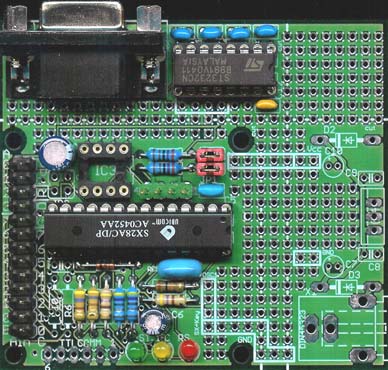
Adapter Pin Connections
All adapter signals (except serial data) are available on a 28-pin header
(2 * 13) with 1/10" spacing.
The signals for the serial interface (TxD, RxD, Signal Ground) are connected
to the 9-pin SUB-D jack.
There is an additional 4-pin header available (1/10" spacing) connected to
the I²C signals SCL, SDA,
and to Vdd (positive supply voltage, and Vss (ground).
The right area of the PCB (not shown in the picture below) allows the
installation of a voltage regula-
tor, the required filter capacitors, and protection diodes and also a DIN
low voltage connector, allowing
to supply the adapter with unregulated DC power (8...12 Volt). In case, the
voltage regulator is not
required, this part of the PCB may be cut off when the footprint size of
the PCB is of importance 56
mm width instead of 65 mm).
Adapter connections, viewed from the component side.
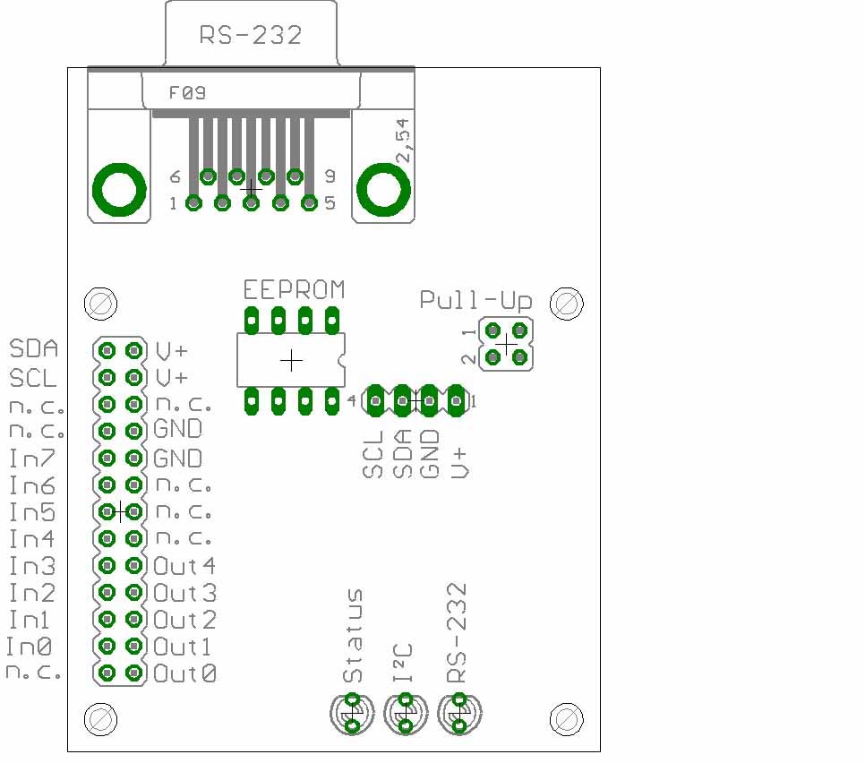
Remarks:
26-pin Header
The 26-pin header is connected to all I/O lines, and to the I²C bus
(SDA/SCL). The pins V+ and GND are used to apply the supply voltage (3.3...5
V DC, stabilized). The pins marked as "n.c." should not be connected because
the are connected to other I/O lines of the SX controller that are used
internally.
4-Pin Header
This header can be used to alternatively connect the adapter to an I²C
bus. It is also possible to feed in the supply voltage here.
Jumper "Pull-Up"
When the two upper, and the two lower pins of this jumper block are connected,
the adapter's internal pull-up resistors between the positive supply voltage,
and the SDA/SCL bus lines are activated. When the jumpers are removed, the
pull-up resistors are de-activated. In this case, it is important that somewhere
else on the bus pull-up resistors are active.
LEDs
The green "Status" LED indicates the adapter's status:
blinking: Adapter is not initialized
steadily on: Adapter is initialized
The yellow "I2C" LED flickers when there are activities on the I²C bus. When the monitor mode is active, this LED is steadily on, and the green Status LED blinks.
The red "RS232" LED flickers on data transfer via the serial RS-232 lines.
SUB-D 9 jack "RS-232"
This jack is used to connect the adapter to the COM port of a PC. There are
only three pins connected:
Pin 2: Adapter TxD PC RxD
Pin 3: Adapter RxD PC TxD
Pin 5: Signal Ground
Component Location "EEPROM
At this location, a serial EEPROM, pin-compatible to types like 24LC01, 24LC02,
etc. may be installed. The three address select bits A0, A1, and A2 (pins
1, 2, and 3) are all connected to Vdd, resulting in a device address of 111
for this EEPROM.
Baud Rate Selection
By default, the RS-232 COM port operates at 115200 Baud to allow for the
highest possible transfer rate between the PC and the adapter. If speed is
not a concern, you may decide to use 38400 Baud instead. At power-on, or
after a BREAK command, the adapter software checks if the controller pins
1 and 25 are bridged. If this is the case, the lower Baud rate is selected.
You can find more information about how to place that bridge in the last
chapter of the Adapter Assembly Instructions.
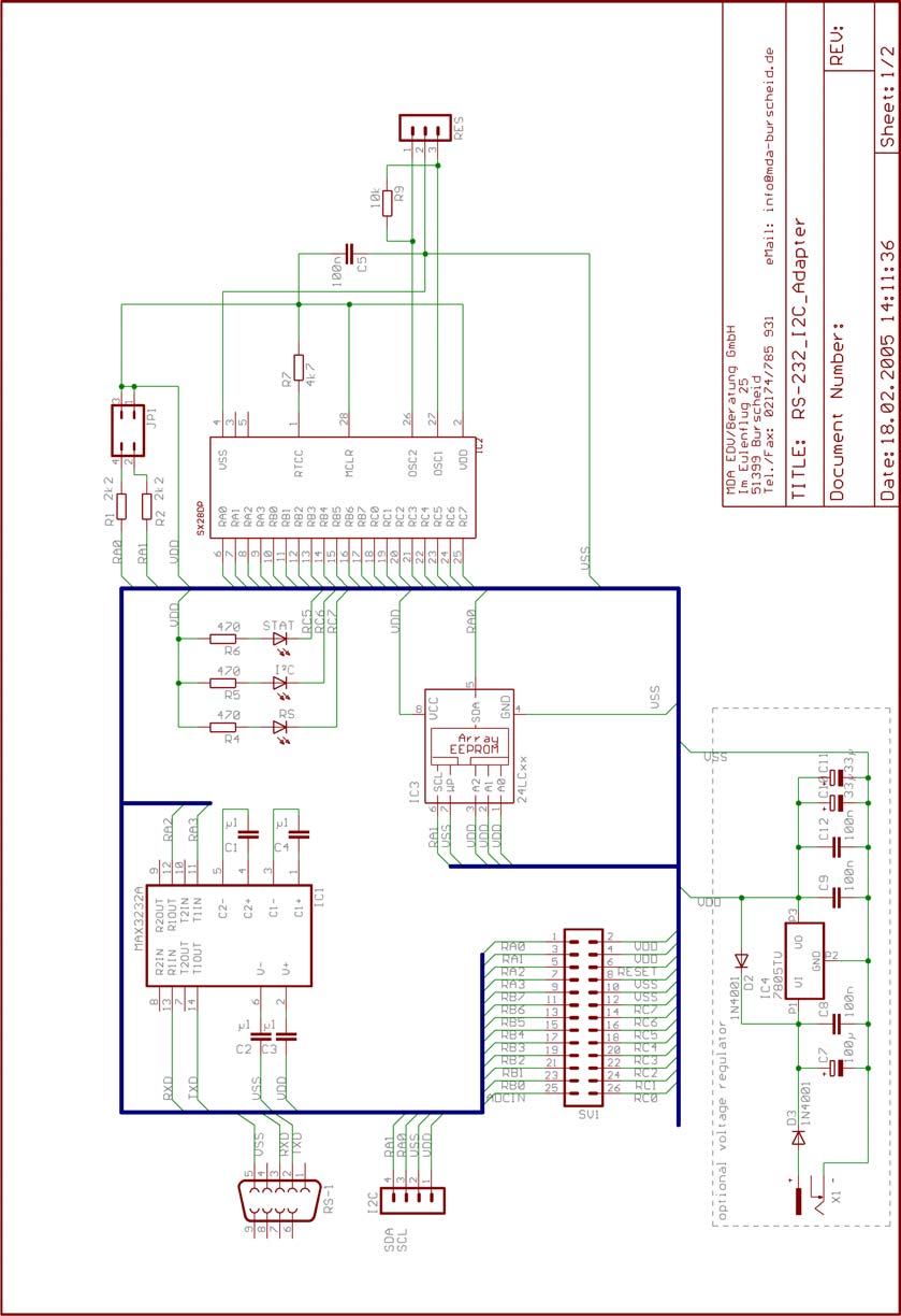
Adapter Schematic
Test Program for the Adapter
The adapter is shipped with a CD-ROM that contains a test application allowing
to test the adapter with a PC. The program was developed in Microsoft Visual
Basic. The source and project files are also distributed on the CD-ROM. You
may use them as hints for your own applications. When the program is launched,
the following window will open:
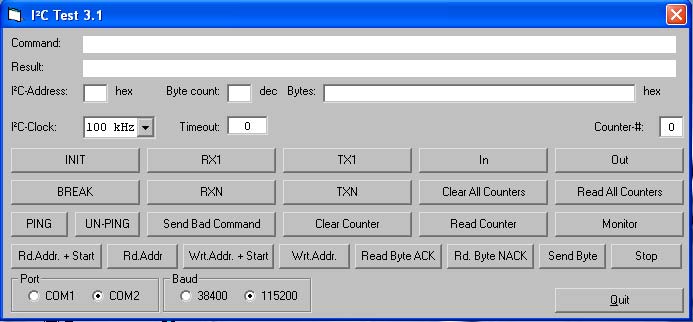
Provided that the adapter has power supply (the green LED is blinking), and that the serial port is connected to one of the PC's COM ports (COM1, or COM2), you may execute the following operations:
Selecting a COM-Port
Click the radio button in the "Port" section to select the COM port that
shall be used for communications.
The buttons described next send various commands to the adapter. The line "Command" shows the characters sent (values enclosed by <> are in hexadecimal). The "Result" line displays the answers being returned by the adapter.
Selecting a Baud Rate
Clock the 38400 or 115200 radio button in the "Baud" section to select the
low or high Baud rate for communication with the adapter. Note that pins
1 and 25 of the adapter's controller chip must be bridged for 38400 Baud.
INIT
This sends an INIT command. If necessary, you may change the defaults
"I²C-Clock", or "Timeout" before sending the INIT. Setting "Timeout"
to some other value but 0 means that you will have to send commands repeatedly.
Otherwise, the adapter would perform a reset after the timeout has elapsed.
After clicking INIT, the adapter's green LED should light steadily, indicating that the initialization was accepted, and the "Result" line should display "Onnn", where "nnn" is the adapter's version number. This has terminated the adapter's idle mode.
Following the initialization, other commands may be sent to the adapter, but it makes sense to send a PING command first.
PING
This command is used to test if the adapter is ready.
UN-PING
This command is no longer supported by adapter versions 3.2 and higher. It
has been left in here, in order the test older adapter versions.
BREAK
This button sends a BREAK command to the adapter. Another INIT command is
required to activate it again.
Sending, and Receiving I²C-Data
Before sending, or receiving I²C data, the address of an I²C component
connected to the bus must be entered in the "I²C Address" field. Please
enter the address in hexadecimal as 7-bit value (i.e. bit 7 is always clear).
The adapter will automatically shift the address bits to the left by one
bit position, and add the read/write bit as LSB.
When the adapter could successfully communicate with an I²C component, the first character returned is an "O". When an error has occurred, an "E" will be returned instead.
Errors will occur when the adapter does not receive an acknowledge from the addressed device. Reasons may be that a bad address has been specified, or that the I²C bus may be broken, or that the addressed component is defective, or does not exist.
RX1
This button sends a read command for a single data byte to the I²C device
with the address specified in the address field. On successful communication,
the "Result" field will contain the sequence "O <xx>", where
<xx> stands for the value read from the device in hexadecimal notation.
RXN
This button sends a read command for one or more bytes to the I²C device
with the address specified in the "Address" field. Before clicking this button,
enter the number of bytes to be received in the "Byte count" field. In case
the device answers, the "Result" field will display "O <xx>
<xx>..." where <xx> contain the bytes read from the device in
hexadecimal.
TX1
This button sends a write command for one data byte to the I²C device
with the address specified in the "Address" field. When the device acknowledges,
the "Result" field will display "O", else it will display "E". Before clicking
this button, enter a hexadecimal value in the "Bytes" field without any specific
characters, e.g. "1d", but not 0x1d, or <1d>. When the "Bytes" field
contains more than one hexadecimal value, e.g. "1d 2a ff aa", the leftmost
one (1d) will be sent.
TXN
This button sends a write command for one or more data bytes to the I²C
device with the address specified in the "Address" field. When the device
acknowledges, the "Result" field will display "O", else it will display "E".
Before clicking this button, enter the number of bytes to be transmitted
in the "Byte count" field, and enter enough hexadecimal values in the "Bytes"
field, each separated with at least one space, without any specific characters,
e.g. "1d 2a ff aa", but not "0x1d 0x2a", or "<1d> <2a>
<ff> <aa>". When this field contains more values than were specified
in the "Byte count" field, values will be read and sent from left to right
from the "Bytes" field until the specified number of bytes has been
sent.
Send Bad Command
This button is used to test the adapter's reaction when it receives an unknown
command (it returns"?" for "unknown command".
Parallel Input/Output
The adapter has eight parallel inputs, and five parallel outputs.
IN
This button issues an INPUT command to read the status of the adapter's parallel
inputs. The Result" field displays "O xx" where "xx" is the hexadecimal value
representing the current status of the eight input bits.
OUT
This button issues an OUTPUT command, setting the five output lines of the
adapter according to the value in the "Bytes" field which must be entered
before clicking the "OUT" button. The upper three bits of this value are
ignored.
Counter Functions
For each input, the adapter maintains a 16-bit counter. Whenever it detects
a rising signal edge on one of the inputs, it increments the associated counter.
These counters can be read and reset individually, or all together.
The buttons "Clear Counter", "Read Counter", "Clear all Counters" und "Read all Counters" are used for these operations. The number in the "Counter-#" field selects the counter for "Clear Counter" and "Read Counter".
Please note that the counter inputs don't perform any de-bouncing. If necessary, external components are required to perform that task. Also, no specific action is taken when a counter overflows from 0xFFFF to zero.
"Low-Level" I²C Functions
In order to communicate with special I²C devices which don't match the
"high-level commands", like TX1, TXn, RX1, and RXn, the adapter provides
these "low-level" functions.
Rd.Addr + Start
This button issues a SEND ADDRESS FOR READ WITH START command, i.e. the start
condition will be set first, and then the 7-bit address in the
"I²C-Address" field together with the r/w-bit set will be sent.
Rd.Addr
This button issues a SEND ADDRESS FOR READ WITHOUT START command, i.e. the
7-bit address in the "I²C-Address" field together with the r/w-bit set
will be sent without setting the start condition prior to sending the address.
Wrt.Addr + Start
This button issues a SEND ADDRESS FOR WRITE WITH START command, i.e. the
start condition will be set first, and then the 7-bit address in the
"I²C-Address" field together with the r/w-bit cleared will be sent.
Wrt.Addr
This button issues a SEND ADDRESS FOR WRITE WITHOUT START command, i.e. the
7-bit address in the "I²C-Address" field together with the r/w-bit set
will be sent without setting the start condition prior to sending the address.
Rd.Byte ACK
This button issues a READ BYTE WITH ACK command, i.e. one byte will be read
from the bus, and the acknowledge bit will be set low. Please note that it
is necessary to issue any SEND READ ADDRESS command in order to select the
desired I²C device for reading before using this function. When you
continuously receive "ff" as the result, it is most likely that no I²C
device has answered because none was addressed before.
Rd.Byte NACK
This button issues a READ BYTE WITHOUT ACK command, i.e. one byte will be
read from the bus, and the acknowledge bit will left high. Please note that
it is necessary to issue any SEND READ ADDRESS command in order to select
the desired I²C device for reading before using this function. When
you continuously receive "ff" as the result, it is most likely that no I²C
device has answered.
I²C devices, like EEPROMs usually allow to sequentially read data, where the sequential read is terminated by sending no acknowledge after the last byte read. This can be accomplished by this function.
Send Byte
This button issues a SEND BYTE command, i.e. the leftmost byte in the "Bytes"
field will be sent via the bus. Please note that it is necessary to issue
any SEND WRITE ADDRESS command in order to select the desired I²C device
for writing before using this function to send a byte. When the I²C
device acknowledges the write operation, an "O" will be displayed in the
"Result" field, else an "E" will be shown.
Monitor
Clicking this button opens the Monitor window:
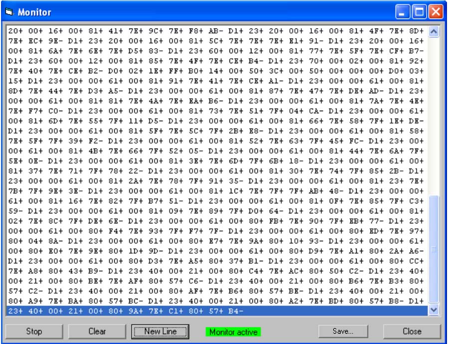
When you click the "Start" button the first time, a MONITOR command will be sent to the adapter which activates its monitor mode. The caption of the "Start" button will change to "Stop" then, and the "Monitor inactive" message changes to "Monitor active".
Now, all bytes the adapter "sees" on the I²C bus will be displayed in the list area of the monitor window in a format like this:
xx+ xx+ xx- xx-
where "xx" stands for the hexadecimal value of the detected byte. The trailing plus indicates that the byte was acknowledged, where a trailing minus indicates that the byte was not acknowledged.
When you click the "Stop" button, the adapter will remain in the monitor mode, and continue receiving characters but they will not be added to the list area until you click the "Start" button again.
You may click the "Clear" button at any time to delete all data displayed in the list area. The "New Line" button inserts a line break at the current position in the list area.
The "New Line" button can be used to insert a line break at the current display position.
The "Save" button opens a file select dialog. Here you may specify the file name used to save the captured data in ASCII text format.
When you click the "Close" button, the Monitor window will be closed, and a BREAK command is sent to the adapter in order to terminate the monitor mode.
Final Note:
This document describes the current adapter software which is subject to
be changed at any time without prior notice.