As an intermediary measure to using full stereometric vision, I have been experimenting with structured-light vision. Structured light vision techniques greatly simplify the process of triangulating the position of a point in space. Using structured light techniques, one can do realtime navigation without lots of horsepower. This is because one is able to project a beam with known coordinates. This provides information about at least one aspect of the geometry in front of the camera, so the triangulation equations are much easier and less computationally expensive.
I think that structured light techniques are far superior to sonar for range and shape measurements in quality and potentially cheaper. They are able to map out the region in front of the camera quickly and accurately. The angular resolution of structured light systems is quite good. Although I have not experimented with sonar systems, based on reports I have read where they have been used, structured light techniques appear far superior. When one considers the cost of acquiring several sonar sensors (which are often expensive), the cost of a structured light system becomes attractive. For example, Kodak 6500 sonar systems typically sell for about $50 each. To get good coverage for a robot might require several of them. A simple structured light system might be cheaper if one considers using something like a cheap black and white camera such as a QuickCam (about $100) with a cheap homebuilt mechanical laser scanner (less than $50). This means a very accurate ranging and mapping device could cost about $150 (not counting the computer needed to process the information).
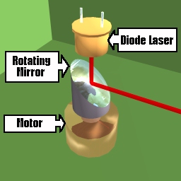
The basic idea with structured light vision is to project a light beam of known geometry onto a scene and then use a video camera to observe how it is distorted by objects. Using simple geometric formulas, one can reconstruct the shape of those objects. Here is an example of a simple kind of scanner. Using a diode laser, it projects light down onto a spinning mirror which is 45 degrees from the vertical axis. This projects a plane of light 360 degrees around the scanner as the motor turns.

One does not have to use a motor-driven mirror to produce the light plane. There are several optical attachments to laser diodes which produce wide planes of laser light without any moving parts. Additionally, one does not have to use a visible laser to perform the scan. Most CCD cameras will detect infrared laser beams quite well (some cameras are more sensitive to infrared light).
Here we see a self-scanning laser diode projecting a beam onto the region in front of it; above is the camera.
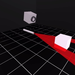
This arrangement would produce the following images.
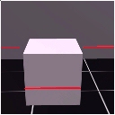
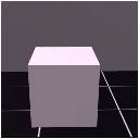
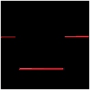
The first image is what the camera sees with the laser on. The second image
is what the camera sees with the laser off. The third image is the mathematical
difference of the two. By subtracting the first two images, only the difference
between them is left: the laser projection. Finally, one may want to filter
the difference image so that the scanned beam appears no thicker than one
pixel. This will aid in map building.
Now that we have a bitmap image of the laser scan on the objects (and knowing the geometry of the scanner and laser), we can reconstruct the geometry of the scene.
Examining a simplified form of the laser projection below, where h is height of the camera above the laser light plane, r is the distance between the camera and the object, y is the y-coordinate of the projection of the laser light on the object as seen on the camera bitmap and f is the focal length of the camera.
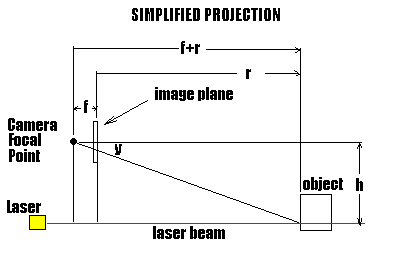
Using simlar triangles, we see that:

Solving for r, we arrive at:

Since we know f and h, we can determine the range, r, as a function of y.
We now merely have to scan the difference bitmap and calculate the range of any pixels that result from the laser projection.
     For y = 1 to Bitmap.YMax
          For x = -Bitmap.XMax to Bitmap.XMax
               If Bitmap.Pixel(x,y) != 0 then
                    ry = f*h/y - f
                    rx = x * (f+ry)/f
                    rz = -h

                   { Now do something with the knowledge        }
                   { that a pixel maps to a particular position }
                   { relative to the camera. Perhaps convert    }
                   { to absolute coordinates and build a map    }
               end if
          next x
     next y
I have written a program, ActiveSim, which implements the above algorithm. It first generates a simulated environment, projects it to a camera view and then builds a map from the visual image. You may download (245K) it here. Unzip it into your desired directory and then read INSTALL.TXT for instructions on installing and running the program. The Visual Basic source code is included.
| file: /Techref/com/cyberg8t/www/http/pendragn/actlite.htm, 5KB, , updated: 2001/1/31 16:43, local time: 2025/10/15 00:23,
216.73.216.155,10-3-165-151:LOG IN
|
| ©2025 These pages are served without commercial sponsorship. (No popup ads, etc...).Bandwidth abuse increases hosting cost forcing sponsorship or shutdown. This server aggressively defends against automated copying for any reason including offline viewing, duplication, etc... Please respect this requirement and DO NOT RIP THIS SITE. Questions? <A HREF="http://ecomorder.com/Techref/com/cyberg8t/www/http/pendragn/actlite.htm"> Robotics: Structured Light Vision</A> |
| Did you find what you needed? |
Welcome to ecomorder.com! |
|
The Backwoods Guide to Computer Lingo |
.